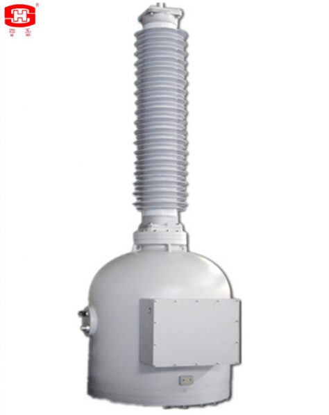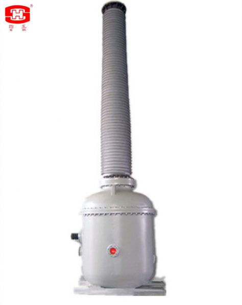


Single-phase Station Service Voltage Transformers gas insulated.
It is a single-phase power transformer which the insulation material is SF6 gas. The bushing of the power transformer is made by silicon rubber or porcelain (for standalone installation). There are some aluminium electrodes inside the power transformer, to improve the electric field distribution inside. There is a pressure relief device at the top of the power transformer, when the pressure is more than 0.8MPa (1.0 MPa only for 500 kV) if the power transformer is discharge inside, the relief device will be broken to release the pressure and send an alarm information. There is a SF6 density monitor fix at the base, it can indicate the SF6 pressure which inside the power transformer (its indicated value is the SF6 pressure at 20℃), and it will provide an information when the SF6 pressure is drop down to the minimum service pressure of the power transformer, to remind the user replenish the SF6 gas to the rated pressure. The secondary terminals block is casted by epoxy resin, the frame of the secondary terminals box is a seal structure, it suits for outdoor. Outline dimensions drawing and structure shown in Figure 1.
一、Service Conditions
a. Ambient air temperature: maximum 40℃, minimum -40℃, average value of the ambient air temperature does not exceed 30℃ measured during a period of 24h.
b. Altitude: The altitude does not exceed 1000m (this is the routine requirement, if there is any different requirement, we can provide the products with 2000m, 3000m, 4000m or 5000m altitude according to the clients’ requirements).
c. The average value of the relative humidity does not exceed 95% at 25℃ measured during a period of one month.
d. The maximum wind speed does not exceed 34m/s.
e. Earthquake intensity does not exceed 8 degree.
f. There have to be no gas that may seriously affect the insulation and conductive ability of electric equipments, steam, ash, salt, chemical deposit, pollution and corrosive or explosive material.
二、Main Technical Parameters.
|
Rated voltage (kV) |
72.5 |
126 |
145 |
170 |
252 |
363 |
420 |
550 |
|
power-frequency withstand voltage (r.m.s) (kV) |
140 |
230 |
275 |
325 |
460 |
510 |
630 |
680 |
|
Rated lightning impulse withstand voltage (peak) (kV) |
325 |
550 |
650 |
750 |
1050 |
1175 |
1425 |
1550 |
|
Rated switching impulse withstand voltage (peak) (kV) |
– |
– |
– |
– |
– |
950 |
1050 |
1175 |
|
Rated output( kVA) |
MAX 333 |
|||||||
|
Secondary voltage |
110~400V,7200~14400V |
|||||||
|
Rated voltage factor |
1.5/30s or others |
|||||||
|
Rate frequency (Hz) |
50/60 |
|||||||
|
Creepage distance( mm/kV) |
25~31 or more high |
|||||||
|
Insulation level |
E/B |
|||||||
|
Accuracy class for metering |
0.2-0.5-1.0* |
|||||||
|
Accuracy class for protection |
3P-6P* |
|||||||
2. Table 2.
|
Table 1Rated voltage (kV) |
Rated output (kVA) |
H (mm) |
W1 (mm) |
W2 (mm) |
D (mm) |
|
72.5 |
25 |
1650 |
400 |
400 |
20 |
|
50 |
1650 |
400 |
400 |
20 |
|
|
75 |
1780 |
600 |
600 |
24 |
|
|
100 |
1922 |
600 |
600 |
24 |
|
|
125 |
1922 |
600 |
600 |
24 |
|
|
126 |
25 |
2005 |
600 |
600 |
24 |
|
50 |
2005 |
600 |
600 |
24 |
|
|
75 |
2272 |
600 |
600 |
24 |
|
|
100 |
2435 |
600 |
600 |
24 |
|
|
125 |
2435 |
600 |
600 |
24 |
|
|
145 |
25 |
2005 |
600 |
600 |
24 |
|
50 |
2005 |
600 |
600 |
24 |
|
|
75 |
2272 |
600 |
600 |
24 |
|
|
100 |
2435 |
600 |
600 |
24 |
|
|
125 |
2435 |
600 |
600 |
24 |
|
|
170 |
25 |
2125 |
600 |
600 |
24 |
|
50 |
2125 |
600 |
600 |
24 |
|
|
75 |
2375 |
600 |
600 |
24 |
|
|
100 |
2568 |
600 |
600 |
24 |
|
|
125 |
2568 |
600 |
600 |
24 |
|
|
252 |
25 |
3670 |
600 |
600 |
24 |
|
50 |
3670 |
600 |
600 |
24 |
|
|
75 |
3822 |
600 |
600 |
24 |
|
|
100 |
3982 |
600 |
600 |
24 |
|
|
125 |
3982 |
600 |
600 |
24 |
|
|
363 |
25 |
4450 |
600 |
600 |
24 |
|
50 |
4522 |
600 |
600 |
24 |
|
|
75 |
4630 |
600 |
600 |
24 |
|
|
100 |
4730 |
600 |
600 |
24 |
|
|
125 |
4730 |
600 |
600 |
24 |
|
|
420 |
25 |
4920 |
600 |
600 |
24 |
|
50 |
4920 |
600 |
600 |
24 |
|
|
75 |
4920 |
680 |
680 |
32 |
|
|
100 |
4920 |
680 |
680 |
32 |
|
|
125 |
4920 |
680 |
680 |
32 |
|
|
550 |
25 |
6220 |
600 |
600 |
24 |
|
50 |
6220 |
600 |
600 |
24 |
|
|
75 |
6438 |
680 |
680 |
32 |
|
|
100 |
6550 |
680 |
680 |
32 |
|
|
125 |
6550 |
680 |
680 |
32 |
|
|
333 |
6550 |
920 |
920 |
32 |
三、Outline dimensions drawing and structure.

Search Results for :