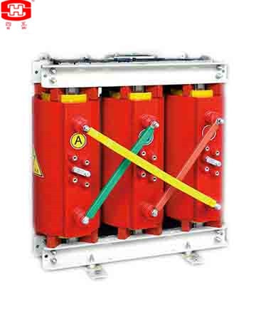
The power transformers are suitable installation for switchgears, and for power plants or substations self-consumption transformers or the places where small space, fire-control, moisture-proof, is needed.
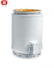
Select of the defend shell: The products can select the beautiful and durable metal shells for more safe. The defend class can select IP20 and IP23 use for indoor. The IP20 shell can prevent the solid things that the diameters are more tham 12mm come into, they are the barriers for the products. IP23 shell can also defend that the drips which are less than 60°with the vertical line come into.
一、Profile of products.
The power transformers are suitable installation for switchgears, and for power plants or substations self-consumption transformers or the places where small space, fire-control, moisture-proof, is needed.
Select of the equipment for forced-air cooling: The cooling method of the product in a general way is natural air cooling, if there is a requirement of the client, we can collocate the system of forced-air cooling for the products of any rated power.
Select of the equipment for temperature display and control: The product can be collocated the equipment for temperature display and control. This equipment can show the temperature of the windings clearly during the product service, and there are many functions such as give an alarm, shut off the power when the trmperature exceed the requirement, turn on and turn off the forced-air cooling, it can be more safe for the product.
Select of the system for microcomputer measure, inspect and control: If the product collocate the microcomputer output connector when it collocate the equipment for temperature display and control, it can select the system for microcomputer measure, inspect and control, to actualize the roboticized manage of power transformer.
二、The functions of this system are as follow:
a) Temperature display and control (give an alarm, shut off the power when the trmperature exceed the requirement, turn on and turn off the forced-air cooling);
b) Electric power measure (can be calaulated the electric power automatically);
c) Inspect the service conditions (current, voltage, temperature, output power, load balance rate, power factor and so on);
d) Deposited the values (can be depositeded 3 years value of the service conditions automatically);
e) Show on line in the microcomputer screen (Show on line of the service conditions);
f) Manage software of the intelligential power transformer ( can be communicated well with person);
g) Printout automatically.
三、Select of the defend shell:
The products can select the beautiful and durable metal shells for more safe. The defend class can select IP20 and IP23 use for indoor. The IP20 shell can prevent the solid things that the diameters are more tham 12mm come into, they are the barriers for the products. IP23 shell can also defend that the drips which are less than 60°with the vertical line come into.
Note: IP23 shell can low down the ability of dissipate heat of the product 5-10%. The structure of the drawing 3 is suit for the indoor product, for the shell of outdoor product must design again.
We can design each kind of shell for the products can be suit for special environment.
四、Technical parameters please see table 1~2
Table 1
|
Voltage Class(kV) |
Rated Short-time Power Frequency Withstand Voltage (r m s) (kV) |
Rated Lightning Impulse Withstand Voltage (peak) (kV) |
|
6 |
20 (or 25) |
60 |
|
10 |
28 (35) |
75 |
|
35 |
70 |
170 |
Table 2
|
Type |
Rated Power (kVA) |
Voltage Combination |
Connection Symbol * |
No-load Loss (W) |
Load Loss (W) (120℃) |
No-load Current (%) |
Impedance (%) |
||
|
HV (kV) |
HV Tapping Range (%) |
LV (kV) |
|||||||
|
SC10-30/10 |
30 |
6 6.3 10 10.5 11 |
±5 or ±2×2.5 |
0.4 |
Yyn0 or Dyn11 |
200 |
710 |
2.6 |
4 |
|
SC10-50/10 |
50 |
280 |
1000 |
2.3 |
|||||
|
SC10-80/10 |
80 |
370 |
1380 |
2.1 |
|||||
|
SC10-100/10 |
100 |
400 |
1580 |
2.0 |
|||||
|
SC10-125/10 |
125 |
480 |
1850 |
1.8 |
|||||
|
SC10-160/10 |
160 |
550 |
2125 |
1.8 |
|||||
|
SC10-200/10 |
200 |
550 |
2530 |
1.1 |
|||||
|
SC10-250/10 |
250 |
630 |
2760 |
1.1 |
|||||
|
SCB10-315/10 |
315 |
770 |
3470 |
0.9 |
|||||
|
SCB10-400/10 |
400 |
850 |
3990 |
0.9 |
|||||
|
SCB10-500/10 |
500 |
1020 |
4880 |
0.9 |
|||||
|
SCB10-630/10 |
630 |
1180 |
5880 |
0.8 |
|||||
|
SCB10-630/10 |
630 |
1130 |
5960 |
0.8 |
6 |
||||
|
SCB10-800/10 |
800 |
1330 |
6960 |
0.8 |
|||||
|
SCB10-1000/10 |
1000 |
1550 |
8130 |
0.8 |
|||||
|
SCB10-1250/10 |
1250 |
1830 |
9690 |
0.8 |
|||||
|
SCB10-1600/10 |
1600 |
2140 |
11730 |
0.8 |
|||||
|
SCB10-2000/10 |
2000 |
2720 |
14450 |
0.6 |
|||||
|
SCB10-2500/10 |
2500 |
3200 |
17170 |
0.6 |
|||||
|
SC10-30/35 |
30 |
35 |
390 |
1150 |
2.5 |
6 |
|||
|
SC10-50/35 |
50 |
450 |
1420 |
2.5 |
|||||
|
SC10-80/35 |
80 |
560 |
1830 |
2.1 |
|||||
|
SC10-100/35 |
100 |
630 |
2090 |
2.1 |
|||||
|
SC10-125/35 |
125 |
700 |
2380 |
1.8 |
|||||
|
SC10-160/35 |
160 |
790 |
2810 |
1.6 |
|||||
|
SC10-200/35 |
200 |
880 |
3320 |
1.6 |
|||||
|
SC10-250/35 |
250 |
990 |
3800 |
1.4 |
|||||
|
SC10-315/35 |
315 |
1170 |
4510 |
1.4 |
|||||
|
SC10-400/35 |
400 |
1370 |
5410 |
1.2 |
|||||
|
SC10-500/35 |
500 |
1620 |
6650 |
1.2 |
|||||
* Clients can appoint a connection symbol different from the above table too, and declare it while ordering.
Note: The highest temperature rise of the products’ windings is 100K, their insulation class is F class, and their cooling mode is AN.
五、Dimensions of the power transformers
For the outline and the installation dimensions please see drawing 1~2 and table 3~4.
Table 3 10kV Power Transformers Installation Dimensions
|
Tpye |
the Installation Dimensions (mm) |
||||||||||
|
H |
H1 |
L |
L1 |
P |
P1 |
E1 |
E2 |
K |
M |
N-D |
|
|
SC10-30/10 |
705 |
— |
749 |
550 |
600 |
550 |
147 |
237 |
259 |
— |
4-Φ14 |
|
SC10-50/10 |
770 |
— |
791 |
550 |
600 |
550 |
153 |
243 |
273 |
— |
4-Φ14 |
|
SC10-80/10 |
815 |
— |
863 |
550 |
600 |
550 |
163 |
253 |
297 |
— |
4-Φ14 |
|
SC10-100/10 |
842 |
— |
892 |
550 |
600 |
550 |
173 |
263 |
306 |
— |
4-Φ14 |
|
SC10-125/10 |
850 |
— |
935 |
550 |
600 |
550 |
176 |
266 |
321 |
— |
4-Φ18 |
|
SC10-160/10 |
930 |
— |
971 |
550 |
600 |
550 |
185 |
270 |
333 |
— |
4-Φ18 |
|
SC10-200/10 |
956 |
— |
998 |
660 |
710 |
660 |
270 |
281 |
342 |
— |
4-Φ18 |
|
SC10-250/10 |
992 |
— |
1067 |
660 |
710 |
660 |
276 |
287 |
365 |
— |
4-Φ18 |
|
SC10-315/10 |
1074 |
— |
1094 |
660 |
710 |
660 |
280 |
291 |
374 |
— |
4-Φ18 |
|
SCB10-400/10 |
1332 |
1327 |
1280 |
660 |
700 |
660 |
270 |
313 |
430 |
138 |
4-Φ13 |
|
SCB10-500/10 |
1367 |
1350 |
1290 |
660 |
700 |
660 |
274 |
320 |
435 |
145 |
4-Φ13 |
|
SCB10-630/10(Uk=4%) |
1537 |
1517 |
1310 |
660 |
820 |
660 |
273 |
323 |
440 |
163 |
8-Φ13 |
|
SCB10-630/10(Uk=6%) |
1342 |
1322 |
1420 |
820 |
980 |
820 |
273 |
323 |
475 |
162 |
8-Φ13 |
|
SCB10-800/10 |
1407 |
1382 |
1480 |
820 |
980 |
820 |
283 |
330 |
495 |
166 |
8-Φ13 |
|
SCB10-1000/10 |
1477 |
1467 |
1550 |
820 |
980 |
820 |
292 |
368 |
520 |
200 |
8-Φ13 |
|
SCB10-1250/10 |
1612 |
1587 |
1590 |
820 |
980 |
820 |
295 |
378 |
535 |
200 |
8-Φ17 |
|
SCB10-1600/10 |
1697 |
1707 |
1690 |
1070 |
1230 |
1070 |
344 |
387 |
570 |
210 |
8-Φ17 |
|
SCB10-2000/10 |
1757 |
1807 |
1850 |
1070 |
1230 |
1070 |
358 |
402 |
615 |
210 |
8-Φ17 |
|
SCB10-2500/10 |
1887 |
1937 |
1910 |
1070 |
1230 |
1070 |
366 |
408 |
640 |
210 |
8-Φ17 |
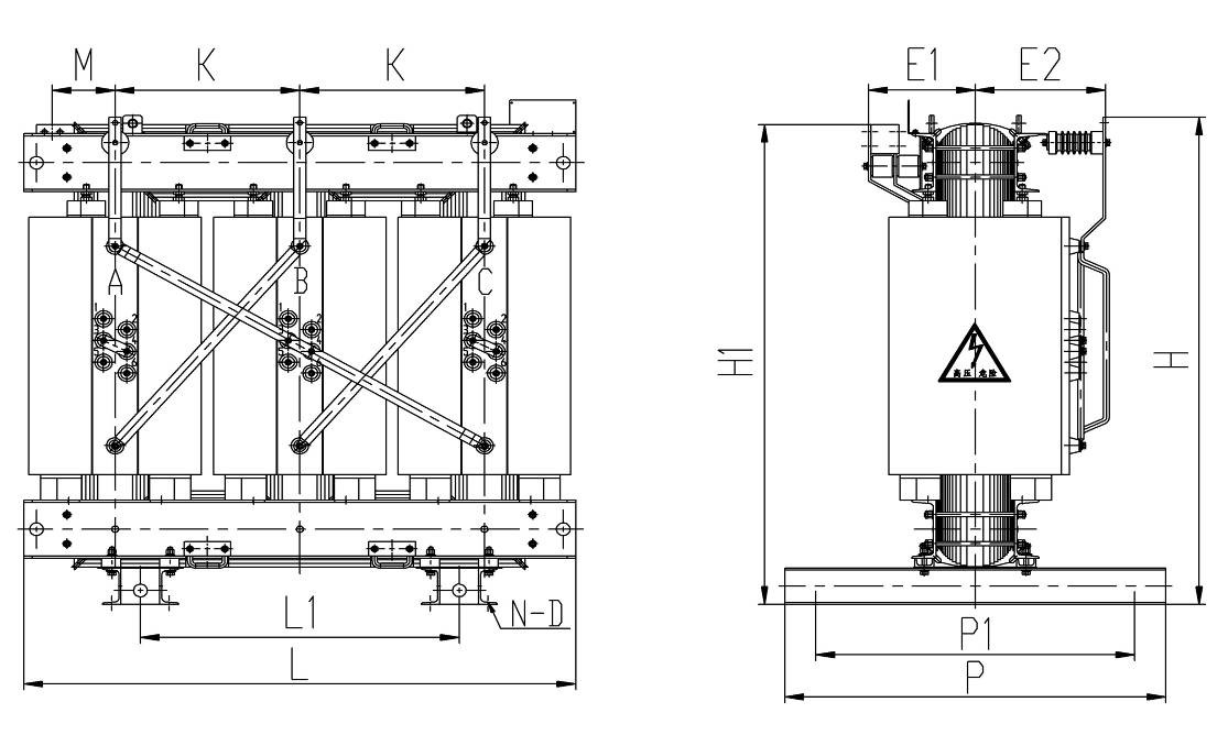
Drawing 1 10kV 30-2500kVA dry-type power transformers outline and installation dimensions
六、Table 4 35kV Power Transformers Installation Dimensions:
|
Tpye |
the Installation Dimensions (mm) |
||||||||||
|
H |
H1 |
L |
L1 |
P |
P1 |
E1 |
E2 |
K |
M |
N-D |
|
|
SC10-30/35 |
1180 |
792 |
1120 |
840 |
280 |
330 |
175 |
475 |
390 |
— |
4-Φ25 |
|
SC10-50/35 |
1120 |
812 |
1120 |
840 |
280 |
330 |
175 |
475 |
390 |
— |
4-Φ25 |
|
SC10-80/35 |
1300 |
860 |
1120 |
840 |
280 |
330 |
175 |
475 |
390 |
— |
4-Φ25 |
|
SC10-100/35 |
1316 |
912 |
1190 |
840 |
310 |
350 |
196 |
418 |
415 |
— |
4-Φ25 |
|
SC10-125/35 |
1382 |
939 |
1190 |
840 |
310 |
350 |
196 |
418 |
415 |
— |
4-Φ25 |
|
SC10-160/35 |
1330 |
895 |
1270 |
660 |
575 |
600 |
210 |
425 |
440 |
— |
4-Φ11 |
|
SC10-200/35 |
1395 |
950 |
1270 |
660 |
575 |
600 |
210 |
425 |
440 |
— |
4-Φ11 |
|
SC10-250/35 |
1425 |
945 |
1365 |
660 |
575 |
600 |
220 |
473 |
475 |
— |
4-Φ11 |
|
SC10-315/35 |
1450 |
945 |
1365 |
660 |
575 |
600 |
220 |
473 |
475 |
— |
4-Φ11 |
|
SC10-400/35 |
1490 |
1005 |
1415 |
820 |
820 |
920 |
295 |
480 |
490 |
— |
8-Φ13 |
|
SC10-500/35 |
1555 |
1015 |
1495 |
820 |
820 |
920 |
305 |
495 |
515 |
— |
8-Φ13 |
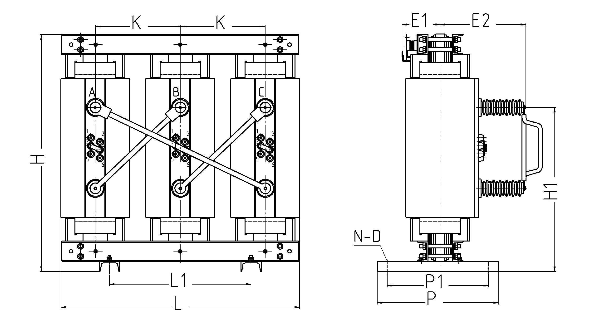 Drawing 2 35kV 30-500kVA dry-type power transformers outline and installation dimensions
Note: The outline and the installation dimensions of table 3 and table 4 are reference for the clients, the actual dimensions are according to the outline of the products.
Search Results for :