
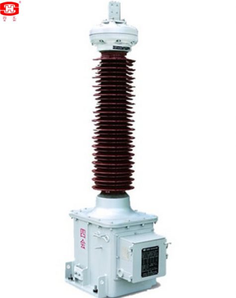

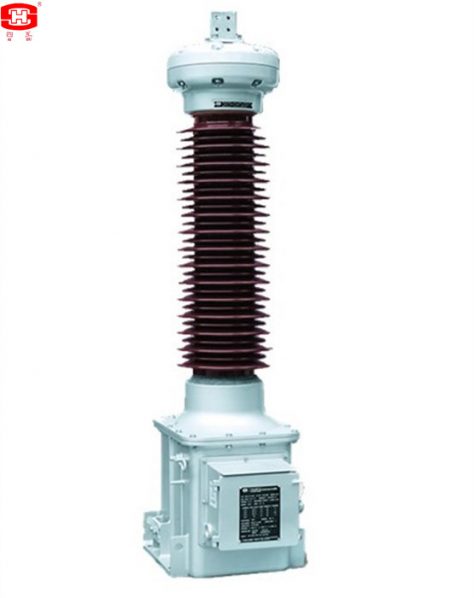
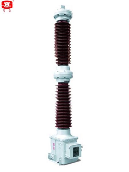
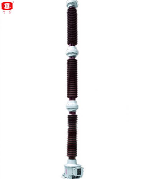
Oil Immersed Capacitor voltage transformer with carrier accessories, also known as coupling capacitor voltage transformer, is abbreviated to CVT.
Capacitor voltage transformer with carrier accessories, also known as coupling capacitor voltage transformer, is abbreviated to CVT. The instrument transformer with carrier accessories shall be suitable for measurement control and relay protection in the outdoor AC power system of nominal voltage 161 kV, BIL750kV, 50Hz and also used for the power line carrier coupling with carrier frequency 50kHz-500 kHz PLC system.
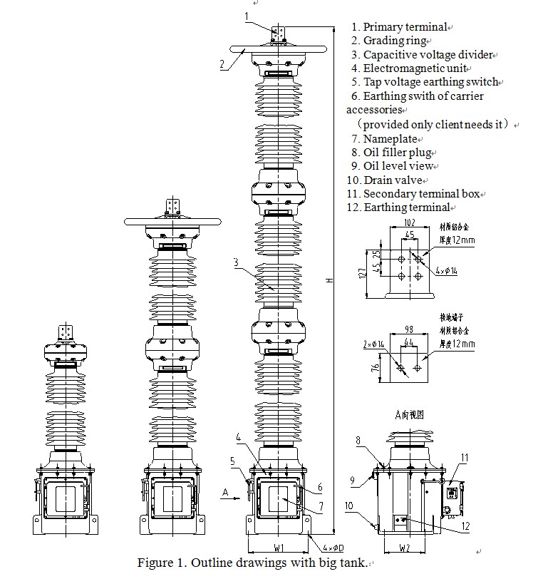
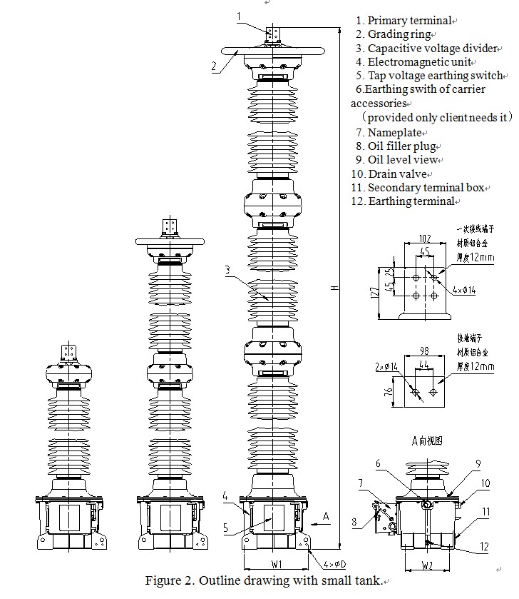
The capacitor voltage divider is mainly composed of porcelain sleeve with flange, bottom sealing plate, capacitor core, upper sealing plate and bellows expander with PXE oil. The electromagnetic unit is mainly composed of cast aluminum case, intermediate transformer, series reactor, anti-resonance device and overvoltage protector, inner part is filled with transformer oil. All parts of the equipment are sealed up limitedly, oil leakage was effectively prevented. The product adopts small design, light weight and novel structure. The product has good insulation performance, can restrain the ferromagnetic resonance phenomenon and run stably. Other devices such as drain rings, spark gap and carrier grounding switches are provided only when the CVT is used as a coupling capacitor for line carrier.
一、Service Conditions
a. Outdoor
b. Ambient air temperature: -45~+40℃(average value of the ambient air temperature does not exceed 30℃ measured during a period of 24h).
c. Altitude ≤1000m(this is the routine requirement, if there is any different requirement, we can provide the products with 2000m, 3000m, 4000m or 5000m altitude according to the clients’ requirements).
d. Application: There have to be no gas that may seriously affect the insulation and conductive ability of electric equipments, steam, ash, salt, chemical deposit, pollution and corrosive or explosive material
e. The average value of the relative humidity does not exceed 95% at 25℃ measured during a period of one month.
f. Max. wind speed ≤34m/s
g. Earthquake intensity ≤7 degree.
二、Main technical Parameters
|
Rated voltage(kV) |
Arcing distance(mm) |
Creepage Distance (mm) |
|
35 |
≥410 |
≥1256 |
|
66 |
≥705 |
≥2248 |
|
110 |
≥1005 |
≥3906 |
|
132 |
≥1160 |
≥4495 |
|
150 |
≥1350 |
≥5270 |
|
220 |
≥2010 |
≥7812 |
|
330 |
≥2700 |
≥11253 |
|
500 |
≥4665 |
≥17050 |
2. Insulation requirements for the primaries please see table 2.
|
Rated voltage (kV) |
35 |
66 |
110 |
132 |
150 |
220 |
330 |
500 |
|
|
Highest Voltage for Equipment (r.m.s.) (kV) |
40.5 |
72.5 |
123 |
145 |
170 |
245 |
363 |
550 |
|
|
power-frequency withstand voltage (r.m.s) (kV) |
95 |
160 |
230 |
275 |
325 |
460 |
510 |
740 |
|
|
The wet test for the current transformer of power-frequency withstand (r.m.s) (kV) |
95 |
160 |
230 |
275 |
325 |
460 |
510 |
740 |
|
|
Rated switching impulse withstand voltage (peak) (kV) |
— |
— |
— |
— |
— |
— |
950 |
1300 |
|
|
Rated lightning impulse withstand voltage (peak) (kV) |
200 |
325 |
550 |
650 |
750 |
1050 |
1175 |
1675 |
|
|
chopped ligtning impulse voltage (peak) (kV) |
230 |
373 |
635 |
750 |
865 |
1208 |
1350 |
1925 |
|
|
Partial discharge level |
prestressing performed voltage (r.m.s) (kV) |
76 |
112 |
184 |
220 |
260 |
368 |
408 |
592 |
|
Test voltage 1.2Um or Um (kV) PD≤10pC |
49 |
87 |
126 |
145 |
170 |
252 |
363 |
550 |
|
|
Test voltage 1.2Um/√3 (kV) PD≤5pC |
28 |
50 |
87 |
100.5 |
118 |
174 |
252 |
381 |
|
Note: Altitude≤1000m, if need to design exceed 1000m, please declare in the order.
3. Table 3
|
Voltage range (kV) |
35 |
66 |
110 |
132 |
150 |
220 |
330 |
500 |
|
Rated capacitance(pF) |
10000 /20000 |
10000 /20000 |
10000 /20000 |
5000 /10000 |
5000 /10000 |
5000 /10000 |
5000 /7500 |
2800 /5000 |
|
Rated frequency(Hz) |
50/60 |
|||||||
|
Rated secondary voltage(V) |
100/√3、110/√3、115/√3 or 120/√3 V etc. |
|||||||
|
Rate output(VA) |
10、15、25、30、50、75、100 VA or it’s multiples |
|||||||
|
Accuracy class |
0.2、0.5、1.0、3.0 or 0.3、0.6、1.2 3P、6P or 0.3、0.6、1.2 Cosφ=0.8 |
|||||||
|
Rated voltage facor |
1.5Un,30s or 1.9Un,8h |
|||||||
|
System earthed |
Neutral point solidly earthed system or Neutral point solidly non-earthed system. |
|||||||
|
Standared |
GB/T 20840.5、IEC 61869-5 or IEEE C57.13 |
|||||||
三、Dimensions of the Voltage Transformers
|
Voltage range(kV) |
No. of capacitor |
Grading ring or not |
H mm |
W1×W2 mm×mm |
D mm |
|
35 |
1 |
× |
1535~1770 |
470×324 |
22 |
|
66 |
1 |
× |
1535~1770 |
||
|
110 |
1 |
× |
1835~2070 |
||
|
132 |
1 |
× |
2035~2270 |
||
|
150 |
1 |
× |
2245~2470 |
||
|
220 |
2 |
× |
3095~3425 |
||
|
330 |
2 |
√ |
3915~4225 |
||
|
500 |
3 |
√ |
5580~6405 |
Notes:
1)There may be any change of the dimensions for the current transformers because of renewing, the clients must basis on the updated drawings.
2)If the product installation dimensions do not meet the requirements, we can provide transitional mounting bracket to meet the installation requirements.
Search Results for :