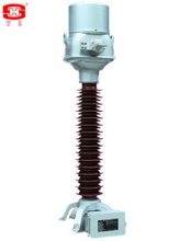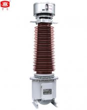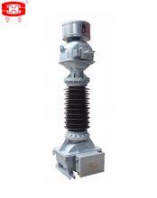
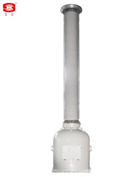
The inductive voltage transformers which the insulation material is SF6 gas. The bushing of the voltage transformer is made by silicon rubber or porcelain.
The inductive voltage transformers which the insulation material is SF6 gas. The bushing of the voltage transformer is made by silicon rubber or porcelain. There are some aluminium electrodes inside the voltage transformer, to improve the electric field distribution inside the voltage transformer. There is a pressure relief device at the top of the voltage transformer, when the pressure is more than 0.8MPa (1.0 MPa only for 500 kV) if the voltage transformer is discharge inside, the relief device will be broken to release the pressure and send an alarm information. There is a SF6 density monitor fix at the base, it can indicate the SF6 pressure which inside the voltage transformer (its indicated value is the SF6 pressure at 20℃), and it will provide an information when the SF6 pressure is drop down to the minimum service pressure of the current transformer, to remind the user replenish the SF6 gas to the rated pressure. The secondary terminals block is casted by epoxy resin, the frame of the secondary terminals box is a seal structure, it suits for outdoor.
一、Service Conditions :
二、Technical Parameters:
三、Rated output and relative accuracy class (cosφ=0.8 lag) please see table 1
Table 1
|
Winding |
Measuring Winding |
Protective Winding |
Residual Voltage Winding |
Winding |
Measuring Winding |
Protective Winding |
|
Terminals Marking Accuracy Class |
1a-1n |
2a-2n |
3a-3n |
Terminals Marking |
1a-1n |
2a-2n |
|
0.2 |
0.5 |
0.5 |
Accuracy Class |
0.2 |
0.5 |
|
|
Rated Output (VA) |
100 |
– |
– |
Rated Output (VA) |
100 |
– |
|
– |
150 |
– |
– |
150 |
||
|
Winding |
75 |
– |
100 |
75 |
– |
|
|
Measuring Winding |
Protective Winding |
Residual Voltage Winding |
Winding |
Measuring Winding |
Protective Winding |
|
|
Terminals Marking Accuracy Class |
1a-1n |
2a-2n |
3a-3n |
Terminals Marking |
1a-1n |
2a-2n |
|
0.2 |
0.5 |
0.5 |
Accuracy Class |
0.2 |
0.5 |
|
|
Rated Output (VA) |
100 |
– |
– |
Rated Output (VA) |
100 |
– |
|
– |
150 |
– |
– |
150 |
||
|
Winding |
75 |
– |
100 |
75 |
– |
|
|
Measuring Winding |
Protective Winding |
Residual Voltage Winding |
Winding |
Measuring Winding |
Protective Winding |
Note: Each thermal limit burden for protective winding is 2000VA.
四、Arcing distance and creepage distance of outer insulation please see table 2.
|
Rated voltage(kV) |
Arcing distance(mm) |
Creepage Distance (mm) |
||
|
Pollution Level Ⅱ (W1) |
Pollution Level Ⅲ (W2) |
Pollution Level Ⅳ(W3) |
||
|
35kV |
≥410 |
≥810 |
≥1013 |
≥1256 |
|
66kV |
≥720 |
≥1450 |
≥1813 |
≥2248 |
|
110kV |
≥1010 |
≥2520 |
≥3150 |
≥3906 |
|
132kV |
≥1160 |
≥2900 |
≥3625 |
≥4495 |
|
150kV |
≥1350 |
≥3400 |
≥4250 |
≥5270 |
|
220kV |
≥2010 |
≥5040 |
≥6300 |
≥7812 |
|
330kV |
≥2360 |
≥7260 |
≥9075 |
≥11253 |
|
380kV |
≥3323 |
≥8400 |
≥10500 |
≥13020 |
|
500kV |
≥3980 |
≥11000 |
≥13750 |
≥17050 |
五、Insulation requirements for the primaries please see table 3.
| Rated voltage (kV) | 35 | 66 | 110 | 132 | 150 | 220 | 330 | 380 | 500 | |
| power-frequency withstand voltage (r.m.s) (kV) | 95 | 160 | 230 | 275 | 325 | 460 | 510 | 630 | 740 | |
| The wet test for the current transformer of power-frequency withstand (r.m.s) (kV) | 95 | 160 | 230 | 275 | 325 | 460 | 510 | 630 | 740 | |
| Rated switching impulse withstand voltage (peak) (kV) | / | / | / | / | / | / | 950 | 1050 | 1175 | |
| Rated lightning impulse withstand voltage (peak) (kV) | 200 | 325 | 550 | 650 | 750 | 1050 | 1175 | 1425 | 1550 | |
| chopped ligtning impulse voltage (peak) (kV) | 230 | 343 | 635 | 750 | 865 | 1208 | 1351 | 1640 | 1930 | |
| power-frequency withstand voltage at the SF6 gas pressure 0MPa (kV) | 30 | 54 | 95 | 109 | 128 | 190 | 272 | 315 | 413 | |
| Partial discharge level | prestressing performed voltage (r.m.s) (kV) | 76 | 112 | 184 | 220 | 260 | 368 | 408 | 504 | 592 |
|
Test voltage 1.2Um or Um (kV) PD≤10pC |
49 | 87 | 126 | 145 | 170 | 252 | 363 | 420 | 550 | |
|
Test voltage 1.2Um/√3 (kV) PD≤5pC |
28 | 50 | 87 | 100.5 | 118 | 174 | 252 | 291 | 381 | |
六、Mechanical requirements for the primary terminals please see table 4.
|
Rated voltage (kV) |
35 |
66 |
110 |
132 |
150 |
220 |
330 |
380 |
500 |
|
Mechanical requirements (horizontal of two directions and vertical) (N) |
— |
500 |
1000 |
1000 |
1000 |
1250 |
1250 |
1500 |
1500 |
|
Applied to the primary terminals with duration (s) |
— |
60 |
60 |
60 |
60 |
60 |
60 |
60 |
60 |
七、Dimensions of the voltage transformers
The outline and installation dimensions please see drawing 1, and the dimensions of the primary termanils please see table 5.
|
Rated voltage(kV) |
H(mm) |
W1(mm) |
W2(mm) |
D(MM) |
|
35 |
1050 |
335 |
335 |
16 |
|
66 |
1500 |
400 |
400 |
20 |
|
110 |
1905 |
450 |
450 |
20 |
|
132 |
2150 |
450 |
450 |
20 |
|
150 |
2350 |
450 |
450 |
20 |
|
220 |
3470 |
600 |
600 |
24 |
|
330 |
4150 |
600 |
600 |
24 |
|
380 |
4720 |
680 |
680 |
32 |
|
500 |
5920 |
750 |
750 |
32 |
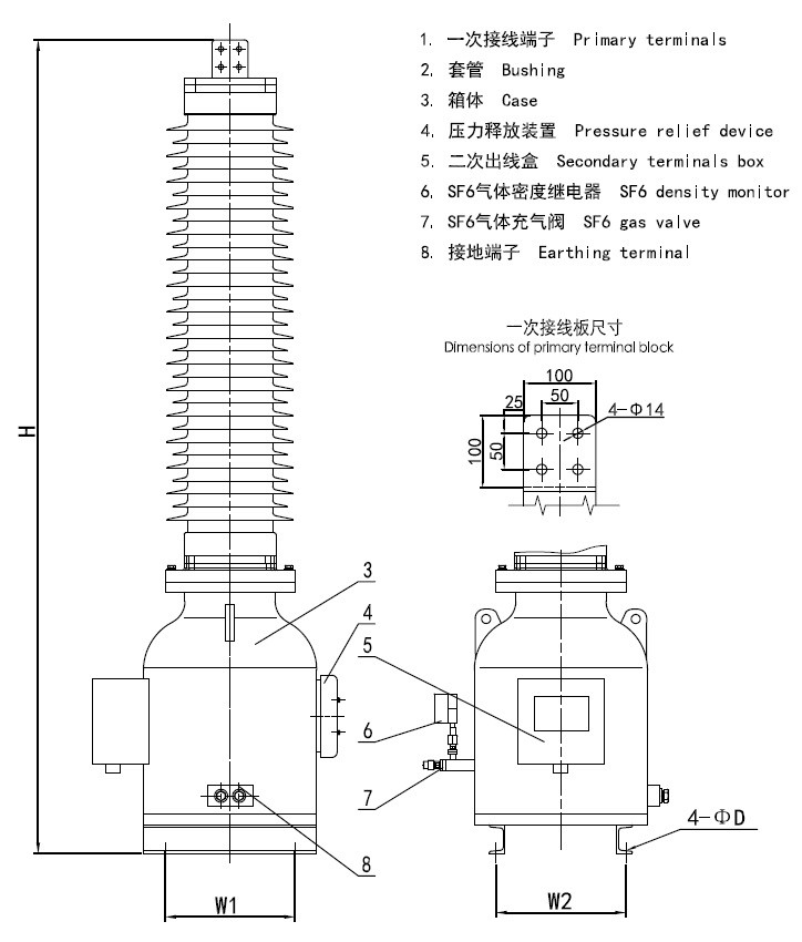
Drawing 1 JDQXF-□W outline and installation dimensions
Search Results for :